
Introduction to VLAN Tagging
Virtual Local Area Networks (VLANs) are integral to modern networking, facilitating enhanced performance and security through network segmentation. VLAN tagging, which is pivotal in managing network traffic, is governed by two principal protocols: 802.1Q and Inter-Switch Link (ISL). For network professionals and those passionate about networking, a deep understanding of these protocols is crucial.
What is 802.1Q?
Referred to as "dot1q," 802.1Q is an IEEE standard that introduces a tagging mechanism in the Ethernet frame header to denote VLAN membership. Its adoption is widespread due to its straightforwardness and the interoperability it offers among devices from different vendors.
What is ISL?
ISL, a proprietary protocol from Cisco, operates differently by encapsulating the original frame with a new header and trailer, which helps in VLAN identification. Though effective, its proprietary nature has led to less common use in the industry.
Comparing 802.1Q and ISL
The fundamental distinction between 802.1Q and ISL is their approach to tagging. 802.1Q incorporates a 4-byte tag directly into the Ethernet frame, whereas ISL wraps the frame with its encapsulation. Each has advantages and drawbacks: 802.1Q is known for its efficiency and broad support, while ISL's unique encapsulation process is sometimes preferred in legacy systems.
The Technical Side of 802.1Q
The structure of an 802.1Q frame is characterized by a tag positioned after the source MAC address. This tag is imbued with VLAN identification and priority details. During the tagging process, a switch will insert this information as frames are forwarded across trunk links.
The Technical Side of ISL
Conversely, ISL's method involves the encapsulation of the whole Ethernet frame, appending a 26-byte header and a 4-byte trailer. This increases overhead but also maintains the integrity of the original frame.
Compatibility and Industry Support
As the industry standard, 802.1Q garners support from a vast range of networking equipment manufacturers. In contrast, ISL's support is more restricted due to its proprietary nature, and it's gradually being replaced by the more universally compatible 802.1Q.
Performance Considerations
Tagging overhead can influence network performance. The 4-byte tag of 802.1Q is relatively insignificant, whereas the encapsulation by ISL introduces more substantial overhead, particularly in environments where high throughput is a necessity.
Security Aspects
Security threats such as VLAN hopping, where unauthorized users may access various VLANs, are a concern in network security. Both 802.1Q and ISL have mechanisms to mitigate this risk, but these must be complemented by meticulous configuration and proactive security practices.
Configuration and Management
The configuration of 802.1Q entails defining VLANs and assigning appropriate ports. ISL configuration is similar but is exclusive to Cisco devices or those compatible with this proprietary protocol.
Troubleshooting Common Issues
VLAN tagging problems, like incorrect VLAN assignments or tagging mismatches, are common issues for network administrators. Addressing these issues typically requires a review and alignment of switch configurations.
Case Studies
Investigations into the real-world use of 802.1Q and ISL provide valuable practical insights. Case studies often highlight the preference for 802.1Q due to its compatibility and user-friendly nature.
The Future of VLAN Tagging
Advancements in network technologies continue to shape the VLAN tagging landscape. While 802.1Q remains predominant, new techniques are emerging that may offer alternative VLAN management solutions.
Conclusion
The prevalent use and efficient tagging system of 802.1Q position it as the preferred choice for VLAN management in contemporary network infrastructures. The proprietary and cumbersome nature of ISL makes it a less attractive option in today's networking context.
FAQs
- What is the primary benefit of using 802.1Q over ISL?
- Is it feasible for ISL and 802.1Q to coexist within the same network infrastructure?
- What impact does VLAN tagging have on the overall performance of a network?
- What security risks are associated with VLAN tagging, and how can they be mitigated?
- What factors should be considered when transitioning from ISL to 802.1Q?
Understanding Switch Port Modes
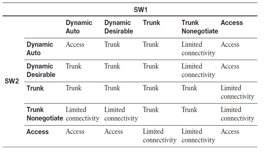
Each switch port can be configured with specific modes to define its behavior in a VLAN environment. These modes are critical in determining how VLAN tagging is applied and how switches communicate VLAN information between each other. The chart below outlines the outcomes based on the configurations between two switches, SW1 and SW2, for different switch port modes:
- Dynamic Auto: A port in this mode will only trunk if the connecting port is set to trunk or desirable. When both are set to auto, they default to access mode.
- Dynamic Desirable: This mode actively seeks to trunk and will do so when paired with another port set to trunk, desirable, or auto.
- Trunk: Sets the port to a permanent trunking mode, ensuring the connection is always a trunk, regardless of the connecting port's mode (except in access mode).
- Trunk Nonegotiate: A fixed trunking mode that does not send DTP frames, useful for devices that do not support or require DTP.
- Access: Configures the port to a permanent access mode, restricting it to a single VLAN with no trunking.
The following matrix illustrates the interaction of SW1 and SW2's switch port modes and the resulting link status:
Each cell in the matrix indicates the resulting state of the link between SW1 and SW2 when configured with the corresponding modes from the table's row and column headers. For example, if SW1 is set to "Dynamic Desirable" and SW2 is set to "Dynamic Auto," the result is a "Trunk" link. If both are set to "Access," the link remains an "Access" link. When incompatible configurations are chosen, such as "Trunk Nonegotiate" on one switch and "Access" on the other, the result is "Limited Connectivity," indicating that the link is not properly functioning for VLAN traffic.
This matrix is essential for network engineers to understand how different configurations will interact, ensuring proper VLAN traffic flow across their network.
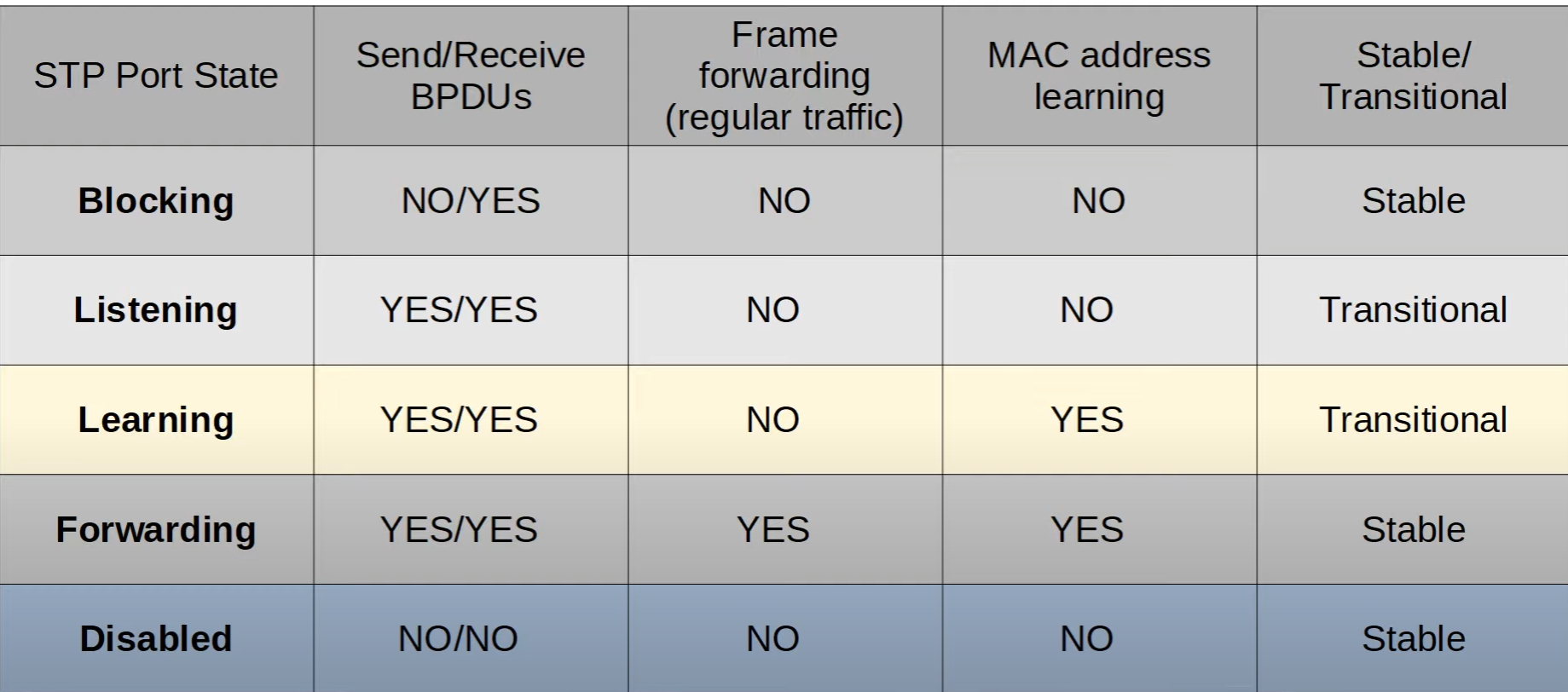
The image provided is a table that outlines the different port states in the Spanning Tree Protocol (STP) and their respective characteristics. STP is a network protocol that ensures a loop-free topology for Ethernet networks. Let's break down each STP port state mentioned in your table:
Blocking
- Send/Receive BPDUs: Ports in the blocking state do not send Bridge Protocol Data Units (BPDUs) but can receive them. BPDUs are messages exchanged between switches to maintain the spanning tree topology.
- Frame forwarding (regular traffic): No, the port in this state does not forward any user data frames.
- MAC address learning: No, the port does not learn MAC addresses in this state.
- Stable/Transitional: Stable, as it's a resting state of the port before possibly transitioning to the next STP state.
Listening
- Send/Receive BPDUs: Yes, ports in the listening state can both send and receive BPDUs, as they are actively participating in the STP process.
- Frame forwarding (regular traffic): No, similar to blocking, listening ports do not forward regular network traffic.
- MAC address learning: No, MAC address learning does not occur in this state.
- Stable/Transitional: Transitional, because the port is in the process of moving from a blocking state towards a forwarding state, but still not forwarding traffic.
Learning
- Send/Receive BPDUs: Yes, learning ports continue to send and receive BPDUs.
- Frame forwarding (regular traffic): No, while the port is learning, it does not yet forward regular traffic.
- MAC address learning: Yes, the port begins to learn MAC addresses to populate the MAC address table, which will be used once it starts to forward traffic.
- Stable/Transitional: Transitional, as it's moving towards the forwarding state but is not there yet.
Forwarding
- Send/Receive BPDUs: Yes, ports in the forwarding state send and receive BPDUs to maintain STP topology.
- Frame forwarding (regular traffic): Yes, ports in this state forward all regular network traffic.
- MAC address learning: Yes, forwarding ports learn MAC addresses to build and maintain the switch's MAC address table.
- Stable/Transitional: Stable, as this is the normal operating state of the port where it is forwarding traffic and maintaining the network topology.
Disabled
- Send/Receive BPDUs: No, disabled ports do not send or receive BPDUs because they are administratively shut down or effectively not in use.
- Frame forwarding (regular traffic): No, no network traffic is forwarded.
- MAC address learning: No, the port does not learn MAC addresses because it is not active.
- Stable/Transitional: Stable, since the port is in a shutdown state and not participating in STP.
These states are part of the STP algorithm that dynamically discovers a loop-free subset of the network. STP prevents network loops, which are undesirable in Ethernet networks as they can cause broadcast storms and multiple frame copies. The transitions from Blocking to Listening to Learning and finally to Forwarding ensure that before a port begins to forward traffic, it is appropriately synchronized with the rest of the network to avoid causing loops. The Disabled state is simply a non-operational state and does not participate in STP.
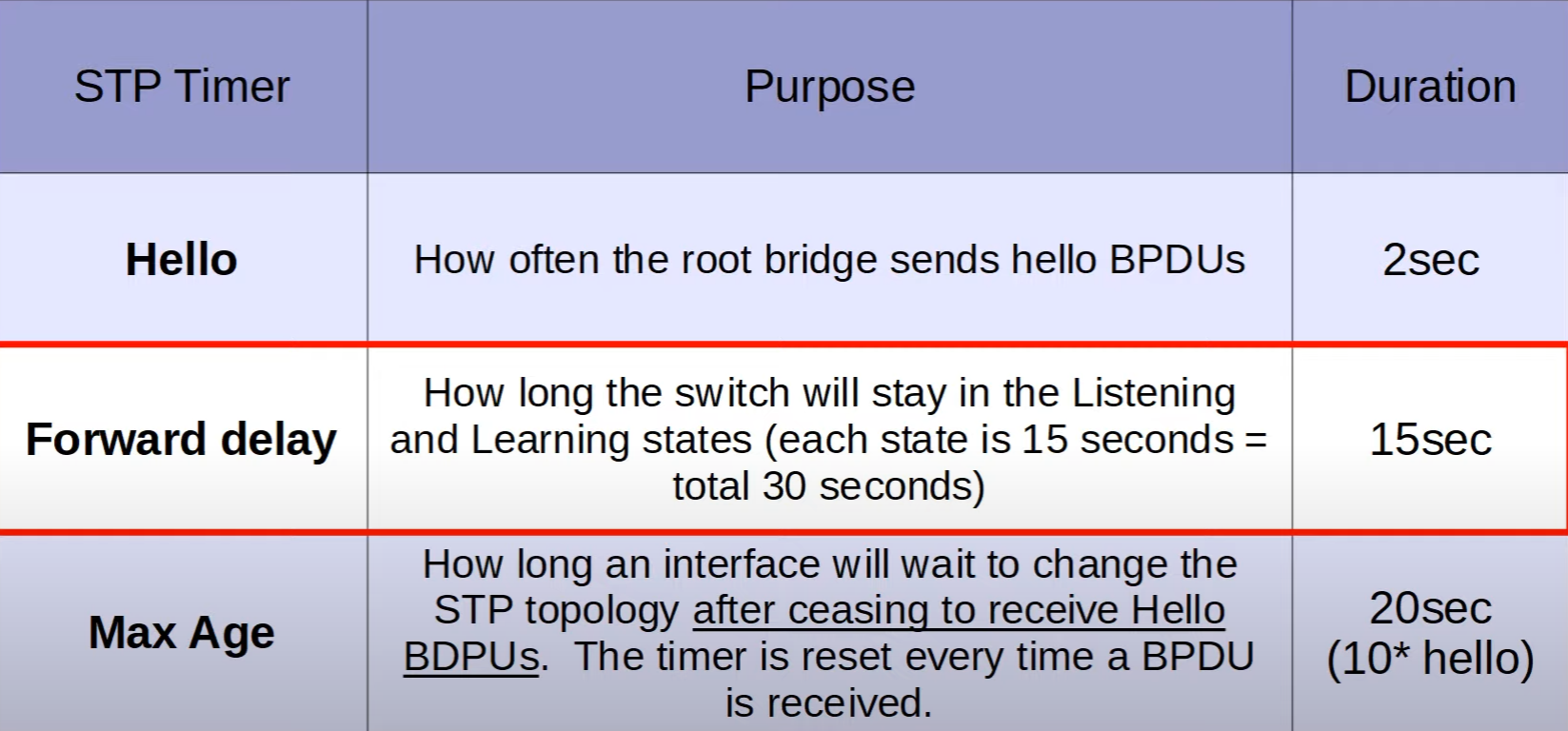
Hello Timer
- Purpose: This timer controls how frequently the root bridge in an STP topology sends out BPDU (Bridge Protocol Data Unit) frames. BPDUs are used for maintaining the STP topology by conveying information about the root bridge and the STP configuration.
- Duration: The Hello Timer is typically set to 2 seconds. This means that the root bridge will send a BPDU every 2 seconds to other switches to assert its role as the root and to maintain the STP topology.
Forward Delay Timer
- Purpose: The Forward Delay Timer is used to determine the length of time a switch port will stay in both the Listening and Learning states. The Listening and Learning states are part of the STP state transition process that a switch port goes through before it starts to forward frames.
- Duration: It is set to 15 seconds. Since each of the Listening and Learning states takes 15 seconds, the total time spent in transition before a port starts forwarding is 30 seconds (15 seconds for Listening and 15 seconds for Learning).
Max Age Timer
- Purpose: This timer defines how long a switch port will wait before changing the STP topology after it stops receiving BPDUs. If BPDUs are not received within this period, the current information is considered stale, and the STP topology can be recalculated. The Max Age Timer also determines the interval that a switch should wait before discarding stale BPDU information and potentially reconfiguring the STP topology.
- Duration: The Max Age Timer is usually set to 20 seconds, which is calculated as 10 times the Hello interval (10 * 2 seconds = 20 seconds). This timer is reset every time a BPDU is received, ensuring that the switch only considers current information for maintaining the STP topology.
These timers are critical in preventing loops and ensuring that the STP topology is stable and reliable. They allow enough time for the network to converge to a loop-free state after any change in topology, such as a switch being added or removed or a link going up or down. Adjusting these timers can affect the network convergence time and stability, so changes to the default values should be made with caution and in accordance with best practices.
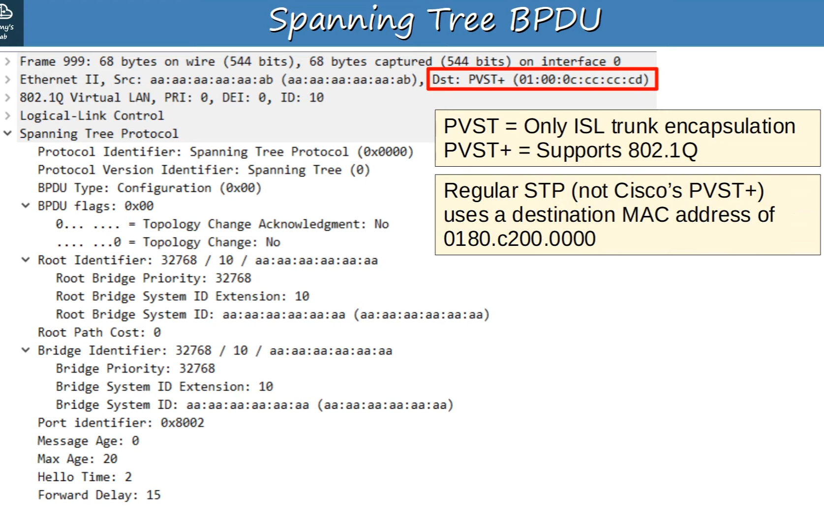
Spanning Tree Protocol (STP) Bridge Protocol Data Unit (BPDU).
A BPDU is a type of network message that is exchanged across the switches within an Ethernet network to detect loops and establish the spanning tree topology. Here's a breakdown of the key elements in the BPDU as shown in your image:
Protocol Identifier: Indicates that the protocol in use is the Spanning Tree Protocol, as expected for BPDU frames.
BPDU Type: The value here indicates a configuration BPDU, which is used for Spanning Tree computation.
BPDU Flags: Provides additional details about the BPDU, such as whether it is an acknowledgment for a topology change.
Root Identifier: Includes the priority of the root bridge and its MAC address. The root bridge is the central reference point for all spanning tree calculations.
Root Path Cost: The cumulative path cost from the current switch to the root bridge.
Bridge Identifier: Similar to the Root Identifier, this includes the priority and MAC address but for the local switch that sent the BPDU.
Port Identifier: Uniquely identifies the port from which the BPDU was sent.
Message Age: Indicates the age of the BPDU since it was originally sent from the root bridge.
Max Age: The maximum age of the BPDU before it is discarded. This is related to the Max Age timer discussed previously.
Hello Time: The time interval between successive BPDUs sent by the root bridge.
Forward Delay: The time that is spent in the Listening and Learning states.
Additionally, the destination MAC address in the Ethernet II header indicates that the BPDU is destined for a multicast address used by switches that support Cisco's Per-VLAN Spanning Tree Plus (PVST+), which is an enhancement over the standard STP. PVST+ allows for separate instances of STP to be run for each VLAN, providing better network optimization and load balancing. The multicast address (01:00:0c:cc:cc:cd) is specific to Cisco and is used to ensure that BPDUs are only received by devices that understand PVST+.
The notation at the top right corner of the image explains that PVST is for ISL trunk encapsulation and PVST+ supports the 802.1Q standard. ISL (Inter-Switch Link) is a Cisco proprietary trunking protocol, while 802.1Q is the industry standard for VLAN tagging on trunk links. PVST+ allows for compatibility with 802.1Q, which is the more commonly used and interoperable protocol in modern networks.